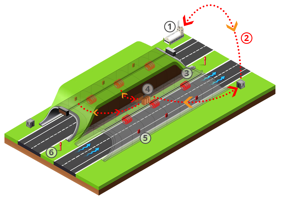


Sensor:
Visibility – measures visibility level in a tunnel
CO – measures the level of CO gases in a tunnel
Temperature - measures temperature in a tunnel
Speed and flow - measures speed and determines flow direction in a tunnel
Sensor:
Fog sensor - it is located in front of the tunnel and detects decrease in visibility caused by fog
This system provides manual and automatic commands for activating ventilators.
All sensors and ventilators are connected to a PLC network which is connected to TMCC.
PLCs are connected to TMCC via Ethernet network. TMCC operators control this system and have pre-programmed scenarios how to react in certain situations.
In case of too much vibration or malfunction on the ventilator motor, TMCC will receive the information about the incident and the operator will be able to choose pre-set scenario on his/her monitor.

PLC is local automatic management controller and interface for remote management.